
CPD Article: Introduction to Air Admittance Valves (AAVs)
Introduction to Air Admittance Valves (AAVs)
Whilst there is a growing awareness and knowledge of the ever-increasing risks to health from the drainage system, it is often given little thought – effectively being out of sight and out of mind – despite it being one of the few building systems that is integrated throughout the whole building. The water trap seal is the only barrier between the drainage system and the living and/or working space; it is therefore essential that this is maintained at all times.
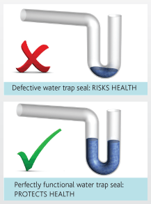
The loss of a trap seal results in unwanted smells, noise and, importantly, the risk of pathogens/disease spreading from the drainage system into the inhabited space. Whilst these are unpleasant in a domestic environment, there are serious health and safety concerns in a commercial environment, where the building owners, landlords and/or occupiers have a duty of care.
What mostly affects water trap seals?
Drainage venting is all about preventing the system pressure from exceeding -400Pa (40mm Wg), i.e. the pressure at which water trap seals will be affected. This would be mostly due to pressure fluctuations (self siphonage, induced siphonage, positive pressure and wind effect) and thermal depletion.
A negative pressure transient occurs when there is a discharge of the fixture to which the trap seal is connected. This can have the effect of reducing the trap seal (or pulling the trap). This occurs as the momentum acquired by the waste passes through the fixture and down the trap seal. This momentum is transferred directly into the trap seal and trap seal loss occurs. This is commonly known as ‘self siphonage’.
Other fixtures discharging in the building can also affect the trap seal. This occurs when there is a pressure fluctuation caused by a discharge of another fixture in the system other than the fixture to which the trap is connected. This is commonly known as ‘induced siphonage’, which is very common in multi-storey/multi-use buildings.
Key venting components of a drainage system
- Trap venting: Venting of a single fixture.
- Group venting: Venting of a group of fixtures, using one vent on the wet side of the last fixture.
- Branch venting: Ventilating pipe connected to a branch discharge pipe.
- Stack venting: Extension of the vertical discharge pipe above the highest branch discharge pipe connection that terminates at an end, open to atmosphere or with an AAV.
- Ventilating stack: Main vertical ventilating pipe, connected to the discharge stack to limit pressure fluctuations within the discharge stack.
- Drain venting: Venting near the end of a main drain or branch drain, the vent being installed on the wet-side of the last fixture.
A combination of the above can be used on larger projects, but these methods have limitations, as open vents require penetrations through the roof to allow the atmospheric air to balance the pressure transients within the sanitary drainage system.
The larger or more complex the system, the longer it takes for the vent at the top of the building takes to react, leading to depletion of the water trap seals. You know when this occurs by just watching and listening. For example, if you see the water in the WC pulling, or listen to the P-trap gurgling, this is an indication venting is inadequate as the traps are being pulled due to the pressure in the system.
Alternatively, Air Admittance Valves (AAVs) can be installed at the Point of Need (PON), near the trap seals that require protection. This has the benefit of eliminating the vent pipe network, the space required and the roof penetrations.
What is an AAV?
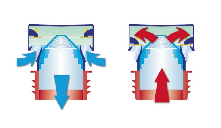
An AAV is a valve that limits pressure fluctuations within the sanitary drainage system by allowing air to enter the system but not to escape. It draws the air, which is required to maintain the trap seals, from the living space where it is installed.
An AAV should open before -75 Pa, allowing air into the system and relieving the negative transient pressure. This keeps the pressures in the system for discharges between 0 and -250 Pa. If the system goes above these pressures, this can lead to the depletion of the trap seals. A typical P-trap will suck dry in less than 1 second if the pressure in the system reaches above -500pa (50mm Wg).
AAVs work by utilizing a reverse lift membrane. When there is water movement in the system the valve will open; when the movement of water stops, the AAV will seal airtight by gravity. AAVs have the effect of slowing down pressure transients in the building and providing air at the PON, eliminating the risk of pathogens leaving the sanitary drainage system and entering the living and/or working space. Most important is that the AAVs are sealed airtight when there is no movement of air in the system.
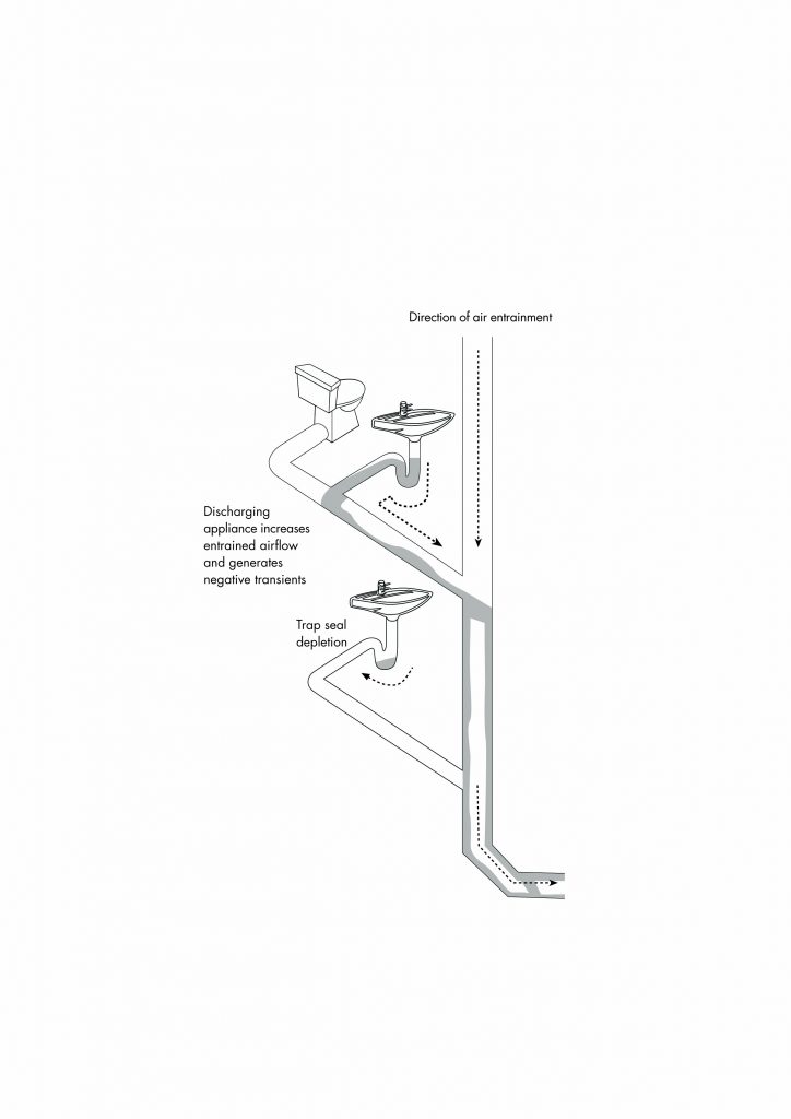
Waste flow without an AAV
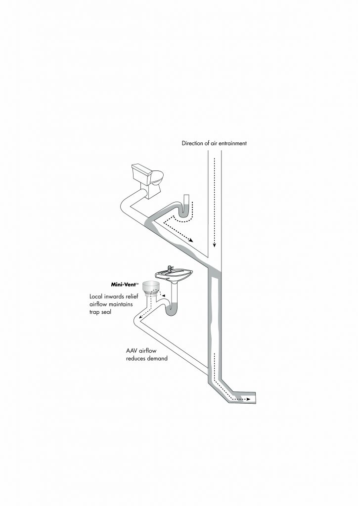
Waste flow with an AAV
Critical aspects of an AAV’s operation
- The need to respond quickly to changes in pressure, every time.
- The necessity to seal completely tight with no leakage whatsoever.
- Longevity of operation; as long as the drainage system itself.
What to look for in a good AAV
Choosing the correct AAV is important. In the UK AAVs must conform to BS EN 12380 and must display the correct information and the CE mark. To further ensure that the AAV is of verified appropriate quality, it is recommended that the valves also have a third party accreditation, for example, a BBA certificate or KEYMARK approval. This provides reassurance that the AAV has undergone rigorous testing at an external testing institute and are routinely assessed.
AAVs that utilize springs, O-rings or clip fit lids should be avoided, as these generally inevitably lead to leakage at low pressures.
Under BS EN 12380 AAVs are rated for performance. An ‘A’ rated AAV can be installed up to 1 metre below the appliance’s flood level and a ‘I’ rated AAV has been proven to operate in extreme temperatures from -20°C to +60°C. Having an AAV that meets the AI or the AII classification will ensure the product is of sufficient quality and performance to provide full protection.
AAV Classification under BS EN 12380
| Determining Factor | Range/Position |
Designation |
Permitted to be located below flood level of connected appliances |
YES | A |
| NO | B | |
Temperature |
-20°C
0°C 0°C
to
to to
+60°C
+60°C +20°C |
I II III |
Written by Steve White
Technical Director DWV
High-Rise Building Solutions
SPECIALIST PLUMBING SOLUTIONS